Acoustic Methods - Problems Of Nondestructive Testing Of Forming Rolls
Abstract—The principal problems that impede the wide use of nondestructive equipment in the opera-tion of forming rolls on sheet rolling mills are studied. The study of the causes for breakdowns of form-ing rolls gave statistically significant distributions of depths and sizes of flaws in the backup rolls. Thecauses of impedances to nondestructive testing of the forming rolls are considered.
DOI: 10.1134/S1061830908040013
The main attention in this paper is drawn to the study of the forming rolls of sheet rolling mills. This isdue to the importance of guaranteeing the quality of the rolled sheet and its substantial dependence on thequality of the forming rolls.
The problems of the quality of the forming rolls have become increasingly important during recent years.A decrease in the number of emergency breakdowns of the forming rolls, which cause stoppages of rollingmills that cost millions of rubles, will help increase in the effectiveness of the rolling production. This raisesinterest in the setup for the automated testing of the forming rolls. An additional advantage of automatedtesting is the reduced role of the human factor during testing and data processing.
One of the most important problems that appear after the completion of the testing and reception of infor-mation about existing flaws is whether there are criteria for estimating flaws. If there are no criteria for esti-mating the presence of a flaw, the information is only qualitative. Can a forming roll with such discontinu-ities still work or should it be replaced immediately?
The problems that accompany the testing of forming rolls can be conditionally separated into twogroups, i.e., methodological and instrumental. First, we shall consider the methodological problems.
In the 1980s, the OST (Branch Standard) 24.023.22–83 [1] and OST 24.023.33–86 [2] standards weredeveloped for the ultrasonic testing of the backup and operation of forged steel rolls of hot and cold rollingmills. In these normative documents, the process of manual ultrasonic testing is specified. All proceduresproposed in these normative documents are only to detect interior flaws in steel rolls.
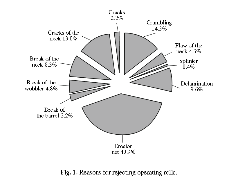
The results of an analysis of the reasons for the unscheduled retirement of more than 500 operating rollsat various metallurgical plants in Russia are shown in the circular diagram in Fig. 1. As follows from thisdiagram, the main cause for the breakdown of operating rolls (more than 85% of the total number) is thepresence of surface flaws. These data agree with the international studies [3].
Initially, a crack propagates over a roll surface before penetrating into its depth. The trajectory of thecrack propagation in metal is at approximately 45° to the surface. It follows from the literature [3] and fromour studies that flaws develop along a trajectory that coincides with the generatrix of the roll.
If a surface flaw is found in time, a premature break in a roll can be prevented via grinding the flaw away.However, the existing normative documents for testing backup and operating rolls, as was already men-tioned, do not include detection of surface and subsurface flaws.
According to the statistics, up to 15% of breakdowns of forming rolls are caused by interior flaws. Breaksin roll barrels are usually a disaster. The roll may cleave longitudinally and/or break into several parts. Aninstantaneous fracture of the barrel due to the overloading of a mill usually propagates over the transverseshear (cleavage) plane at an angle of 45°.
During nondestructive testing (NDT) of rolls, surface and the interior flaws should be detected. In orderto find surface flaws, Rayleigh waves can be used. However, when ordinary piezoelectric probes (PEP) areused, many false reflections from drops of contact liquid are detected. The use of an electromagnetic acous-tic probe (EMAP) solves the problem of false reflections. However, this requires special equipment; more-over, the equipment for eddy current detectors (ECD) is simpler and provides higher sensitivity of testing.
The practice shows that the eddy current testing is the most effective for automated detection of surfaceflaws. Ultrasonic testing is most effective for finding interior flaws.
There are other problems that complicate the nondestructive testing of forming rolls, including the fol-lowing:
Testing forming rolls to detect surface flaws is not regulated.
Ultrasonic testing of iron (single- and double-layer) rolls is not regulated.
The procedures of eddy current, magnetic, and visual-measuring methods for testing of the forming rollsare not regulated.
Automated testing is not regulated, etc.
Nondestructive testing procedures for forming rolls should be specified more clearly. In the oppositecase, they are ambiguous. This causes a conflict between suppliers and customers. The author of this paperwas a witness of the conflict between a supplier and a customer of forming rolls, which was caused by dif-ferent interpretations of the normative document. The same statements of the actual document were differ-ently interpreted.
The complete testing of forming rolls can be performed by the complex application of various NDT tech-niques. The NDT techniques shown in Table 1 can be efficient for both the manual and automated testingof forming rolls.
Most of the currently operating rolls are made of iron. Until recently, there was no such nondestructivetesting in Russia, if not to take into account visual observation, which is also not specified.
Table 1. Recommended NDT methods for testing forming rolls
| Type of testing | Manual NDT | Automated NDT | ||
|---|---|---|---|---|
| surface flaws | interior flaws | surface flaws | interior flaws | |
| Visual-measuring testing | + | -- | + | -- |
| Eddy-current | + | -- | ++ | -- |
| Ultrasonic nondestructive testing | ++* | ++ | - | ++ |
| Magnetic nondestructive testing | + | -- | - | -- |
| Complex methods of nondestructive testing | + | -- | -- | -- |
Note: The symbols show the efficiency of using one or other technique: ++ good; + satisfactory; – unsatisfactory; – – unsuitable;
* in order to find surface flaws, surface waves are used.
Table 2. The effect of the operating roll type on the longitudinal wave velocity
| Manufacturer | Average velocity of the longitu-dinal wave, m/s | Standard deviation of the longitu-dinal wave velocity, m/s |
|---|---|---|
| SSTM (Russian Federation) | 5289 | 133 |
| Akers (Belgium) | 5768 | 20 |
| GP (Germany) | 5854 | 22 |
| Czech Republic | 4931 | 68 |
| France | 5711 | 12 |
| DZPV (Ukraine) | 5247 | 245 |
| Slovenia | 5747 | 31 |
We have studied the possibility of the ultrasonic testing of single- and double-layer iron rolls at frequen-cies of 0.6, 1, 2, and 5 MHz. As a result of this series of experiments, it has been found that ultrasonic testingof all types of operating rolls is possible at frequencies of up to 1 MHz. In this case, a distinct bottom signalis detected for all types of iron rolls. Testing at higher frequencies is also possible depending on the type ofthe roll iron (globular iron, gray iron, etc.). For example, a bottom signal was detected, even at a frequencyof 5 MHz during testing of Akers (Belgium) and GP (Germany) rolls with a barrel 700 mm in diameter.
Taking into account the abovementioned, a frequency of 1 MHz can be recommend for the ultrasonictesting of all types of operating iron rolls. Then, the velocities of longitudinal waves in iron rolls of differentmanufacturers were measured at a frequency of 1 MHz. The first and second types of bottom signals weredetected on all types of operating rolls. The passing time between the first and second bottom signals at theknown diameter of the roll was measured. The measurements were performed on more than 600 operatingrolls.
As is seen from Table 2, the velocity of the longitudinal waves in operating rolls changes significantly.
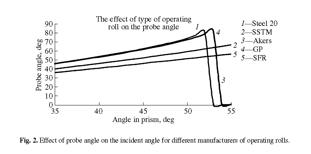
This is caused by a difference in the structures of the iron rolls. As a result, the velocity of the transversewave also changes. This causes great errors in determining the coordinates of flaws if the probe angle isadjusted at the calibration block (CB-2).
Thus, for example, it is shown in Fig. 2 that, at a prism angle of 50° corresponding to a probe angle of65° on the CB-2, the real probe angle at the Akers roll will be 52°. This shows the necessity of taking intoaccount the real velocities of transverse waves in forming rolls and, if necessary, to make corrections.
In order to obtain data on the depth distribution of flaws in backup rolls, the results of the standard ultra-sonic testing of more than 300 steel backup rolls were analyzed at the rolling mills 1700 and 2800.
In Fig. 3, the distribution of flaws in relative depth in backup rolls is shown as a histogram. The relativedepth was found as the ratio of the absolute depth of a flaw to diameter D of the roll in which the flaw wasdetected.
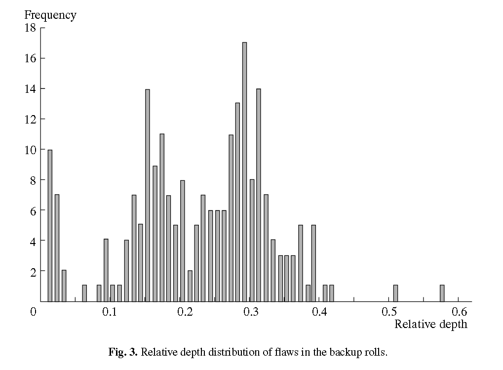
This distribution has several maxima, the first of which is related to the surface and subsurface flaws; thesecond is observed at 0.15D of the roll. The next maximum corresponds to 0.3D of the roll.
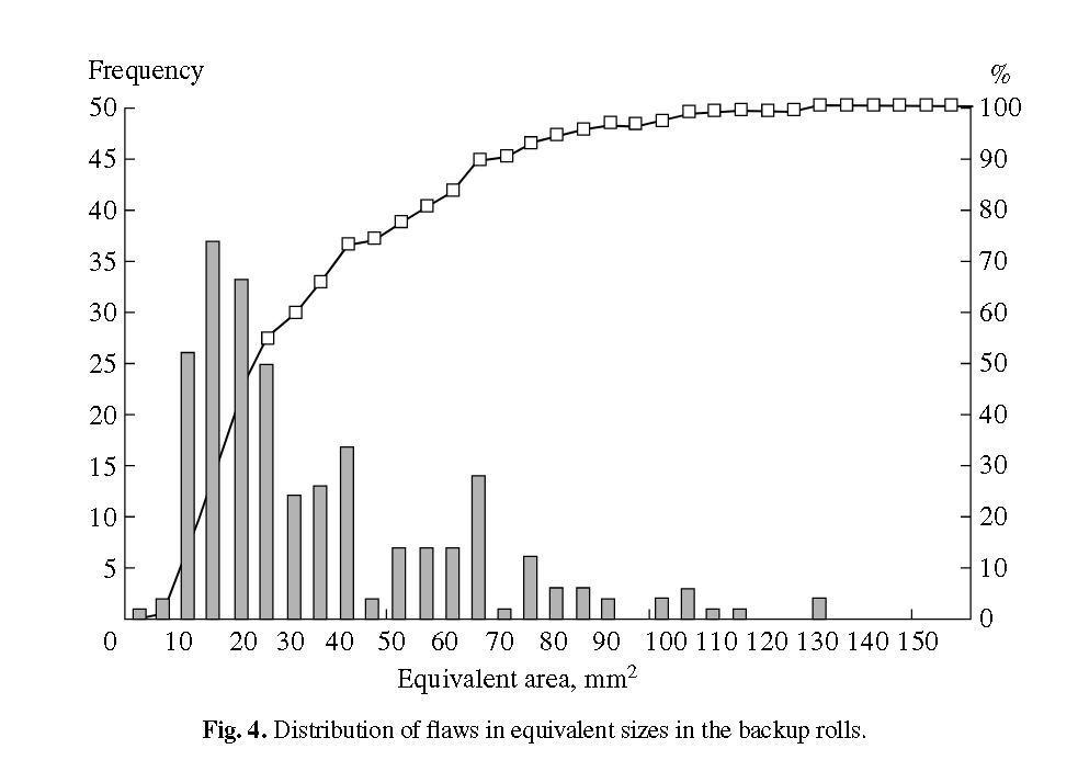
The flaw was characterized by the equivalent area Se (mm2) during ultrasonic testing. In Fig. 4, the his-togram of flaw distribution in equivalent sizes is shown for backup rolls.
According to the acting document [2], the acceptance level during ultrasonic testing of backup rolls withlongitudinal waves is 87 mm2. At the detection level 6 dB higher than the acceptance level, the sensitivityis 43.5 mm2. As is seen from this curve, more than 70% of flaws in this case are not detected.
-a-defective-area-and-(b)-an-equivalent-ellipsoid.png)
If the search level is increased to 5 mm2, this will cause an increase in the detectability of flaws of up to95% and will also provide monitoring of development of interior flaws.
Presently, automated setups for testing rolls at the rolling mills are developed and produced abroad. Allof these setups are intended for detecting surface flaws. A comparative analysis of the setups for nondestructive testing of rolls is considered in [4]. Foreign setups for the nondestructive testing of forming rolls areusually integrated in a roll-grinding machine.
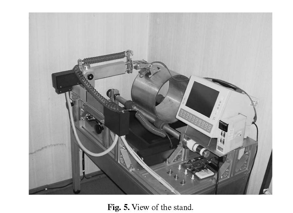
We have developed a stand (Fig. 5) on which methodological and instrumental criteria of the operationof the automated setup are chosen. A forming roll was simulated by a piece of thick-wall aluminum tube. Change in the driving gear rotation velocity determined the change in the linear motion velocity of theprobes from 0 to 1500 mm/s. The longitudinal motion of the scanning system can be changed from 0 to100 mm/s.
To find coordinates, absolute rotation sensors were used. It was decided that the cable connection shouldbe rejected when information was transmitted from the coordinate sensors. A wireless channel for datatransmission was developed. One of the advantages of the proposed technology is use of an unlicensedradio-frequency range and a low radiation power, which frees one from the necessity of registering thesetransmitting devices in Gossvyaz’nadzor (State Agency for Communication Supervision) organs andreduces its effect on other electronic equipment. A high transmittance rate of up to 1 Mb/s was achieved.
Great experimental work performed on the stand provides finding of the optimal conditions for eddy-current and ultrasonic testing of the forming rolls.
Taking into account the drawbacks of foreign setups, recommendations from the manufacturers, andexperience in work on this stand, a model series of automated setups was developed at the Central ResearchInstitute for Machine-Building Technology. Additional channels are included in the setup depending on theproblems that must be solved. One standard size of a case with an IP65 degree of safety from external effectsis used for uniformity in all models. Industrial TFT sensor panels with high brightness (>300 cd/m2) are usedas a display.
A variant of the automated setup developed only for detection of the surface flaws is used. A special mul-tichannel eddy-current probe is used to detect and estimate the surface flaws with penetration depths of0.15–5 mm.
This setup is used to test both the operating and backup rolls of rolling mills and serves as an operatingtool of a grinder. A large sensor screen and a friendly interface facilitate the process of controlling the setup.An operator does not need to have knowledge and qualification of a specialist in nondestructive testing. Theresults of the testing are displayed on a colored screen as a 2D scan. The grinder can estimate the depth ofa detected flaw and make a decision on grinding a flaw away or sending the roll to more comprehensive test-ing.
The maximum linear testing rate may reach 2 m/s. An operating roll can be tested for 2–5 min, whiletesting of a backup roll takes 10–15 min. After testing is completed, the results are saved in the central com-puter. The data are transmitted automatically after the testing. In order to transfer information, a built-inmodule of wireless communication working in the Wi-Fi standard is used.
In order to visualize interior flaws detected by the ultrasonic channel, software was developed using theRBF algorithm [5]. The result of visualization of a defective zone is shown in Fig. 6a. To draw an equivalentellipsoid, the least-squares method was applied and used to minimize the sum of squares of the distancesfrom points determined by vertexes of triangulation to the given ellipsoid. The result is shown in Fig. 6b.
The ultrasonic testing completed within a few minutes brings to the results that cannot be obtained bymanual testing. This precise localization of defective zones and the numerical values of these zones (a vol-ume, an area of any section, etc.) not only makes it possible to detect and characterize defective zones, butit also provides their monitoring. The obtained results provide predictions of the operational life of rolls onthe basis of more precise information for strength calculations.
The main advantages of the proposed setups are the friendly interface in Russian, high precision of deter-mining flaw coordinates, the possibility of testing roll necks, use of wireless channels for information trans-lation, etc.
CONCLUSIONS
In the normative documents, it is necessary to envisage testing of the forming roll surfaces using ultra-sonic and eddy-current testing.
Knowing that ultrasonic testing does not cause fundamental problems, it should be recommended in thenormative documents to use ultrasonic testing of iron rolls at a frequency of 1 MHz.
Taking into account that double- and multilayer rolls are coming into increasingly wide use in the rollingindustry, the testing of these rolls should be included in the normative documents.
Different acceptance levels of flaws depending on their depth should be included in normative docu-ments.
