Acoustic Methods - Automated Devices For The Testing Of Mill Rolls
Abstract—Multichannel "ВАЛОК"-type devices developed at TsNIITMASh for the automated ultra-sonic inspection of cylindrical objects, such as mill rolls, shafts of turbines and compressor units, circu-lar welded joints of thick-walled shell rings, etc., are described. These devices feature from two to eightacoustoelectronic channels. Acoustic contact occurs through industrial water. The testing is performedunder workshop conditions; the object being inspected is rotated by a turning lathe or any other handlingmechanism. Sonication is simultaneously performed by piezoelectric transducers (PETs) with inputangles of 0, 40, 50, 60, and 70° and also by surface and head waves in order to reveal surface and sub-surface flaws. A wide-span eddy-current transducer of special design is also used for this purpose. Alldata are stored in flash memory and retrieved on a PC located in an office. The inspection results aredisplayed as C- and B-type scanning defectograms. Moreover, it is possible to obtain an isometric imageof flaw zones. “ВАЛОК”-type devices have been used for over one and a half years in two workshopsat OAO Severstal’.
The problem of the quality of working and supporting rolls is of particular importance in the metallur-gical industry. This is because of the considerable economic losses incurred during emergency shutdownsof a roll mill due to the breakup of rolls. The use of nondestructive testing during both the manufacture andexploitation of rolls, as well as during scheduled reconditioning of rolls, is a realistic way to ensure the max-imum efficiency of a mill and to increase the quality of the products.
The available data and foreign experience show that surface and subsurface flaws, cracks in particular,constitute one of the main reasons for the breakup of rolls. According to statistics, 95% of roll breakupsresult from surface and subsurface flaws, and only 5% of breakups are due to internal flaws [1].
The implementation of nondestructive-testing methods is complicated by the fact that currently there isneither adequate regulatory documentation that standardizes the inspection of the roll quality (especiallycast-iron rolls) by these methods nor a list of well-founded norms of tolerable flaws differentiated dependingon the flaw type and its orientation and localization (internal and surface flaws).
The technology suggested by the active OST (branch standard) 24.023.22–83 [2] for the ultrasonic test-ing of supporting rolls of rolling mills manufactured in accordance with OST (branch standard) 24.013.04-90E does not even stipulate the necessity of detecting surface and subsurface flaws. This OST is intendedfor detecting gross internal flaws in steel supporting rolls by ultrasonic testing as the only method. Atpresent, the majority of working rolls are made of cast iron.
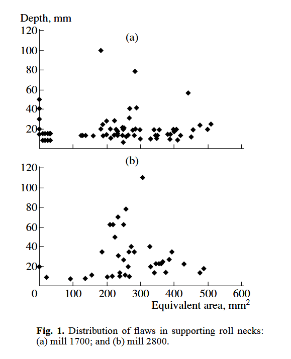
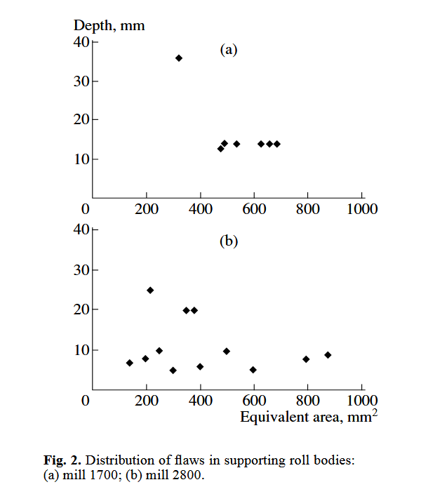
To obtain data on the depth distribution of flaws in supporting rolls, we have analyzed the results of ultra-sonic testing of over 200 rolls at rolling mills 1700 and 2800 at AO Severstal’ for the period 1999–2002.Since the testing was performed at a certain preset sensitivity, the flaws were analyzed only if the signalsfrom them exceeded this level. Therefore, the dependences obtained reflect the distributions of only part ofthe flaws detected. The equivalent surface Se was taken as the parameter characterizing the flaw size.
Data on the ultrasonic testing of roll necks and roll bodies were analyzed separately. Figures 1 and 2show the results obtained. It follows from the plots that the majority of flaws in roll necks have been detectedat depths from 0 to 400 mm, whereas flaws in roll bodies have mostly been found at depths from 100 to800 mm. These data give sound evidence that it is necessary to inspect the entire bulk of rolls, including rollnecks.
Eddy-current testing allows surface flaws (such as spalling cracks, deteriorating cracks, bruises, andburns from a grinding wheel) to be detected in good time; this makes it possible to prevent the chipping anddeterioration of rolls.
Internal flaws in rolls are detected most efficiently by means of ultrasonic testing. Statistics over many yearsshows that manual ultrasonic testing does not ensure the detection of all intolerable flaws. Moreover, the pro-ductivity of the process is small, and documenting of the testing results is a time-consuming procedure.
The application of automated ultrasonic and eddy-current testing is a feasible way for decreasing the rateof emergency breakdowns of mill rolls.
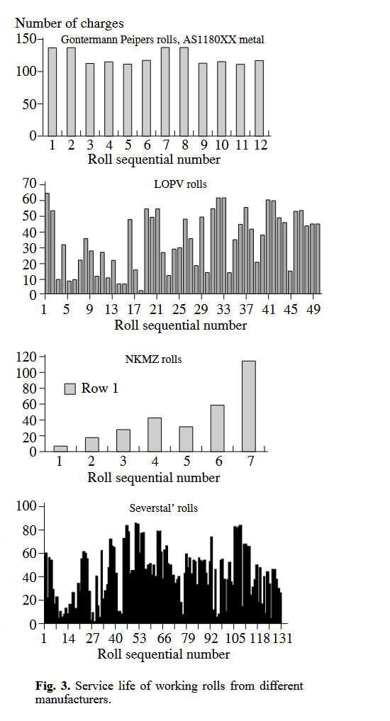
The bar charts in Fig. 3 show the lifetimes of working rolls from different manufacturers. According toavailable data, the working rolls made by foreign manufacturers undergo ultrasonic and eddy-current test-ing. As a result, these products have longer service lives.
At present, many foreign companies manufacture automated devices for testing mill rolls: LISMAR(Netherlands), SARCLAD (Great Britain), Kantoc (Japan), Innerspec Technologies Inc. (USA), etc. Thesedevices are used both at the manufacturing stage and during the operation of rolls.
The table lists the main parameters of these devices. One can see from the table that these devices mostlyuse direct PETs for detecting internal flaws. However, such PETs are only efficient for detecting flaws ori-ented parallel to the surface being scanned.
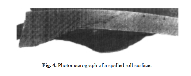
A crack in the metal propagates along a path oriented at an angle to the surface. This is demonstrated bya photomacrograph (Fig. 4) of a spalled surface of a roll. One can see from the fragmentary literature data[3] and from this photomacrograph that flaws propagate along a path coinciding with the generatrix of a roll.In order to detect such flaws, the PETs should be oriented transversely to the roll generatrix.
Of course, a direct PET is unlikely to detect a flaw with such an orientation. Furthermore, the inspectiondepth is limited to 150 mm, whereas the diameters of supporting rolls can be as large as 1700 mm. Thus,inspection by such devices leaves a major part of rolls' cross sections untested for the presence of deep flaws(see Figs. 1 and 2).
In foreign devices, surface and subsurface flaws are mostly detected using eddy-current probes.
Surface waves are used for this purpose only in the device developed in Japan [4]. To eliminate the effectof the contact liquid on the testing results, a special liquid removal system is used.
TsNIITMASh has developed the following automated devices for testing mill rolls: ВАЛОК-2,"ВАЛОК-5", and ВАЛОК-9.
TECHNICAL PARAMETERS AND THE FIELD OF APPLICATION OF DEVICES
The two-channel device ВАЛОК-2 is intended forthe automatic monitoring of the working and support-ing mill rolls. It is designed as a tool for a grinder. Itsmain difference from foreign analogs is that it canadditionally test roll necks. The operating procedure issufficiently simple for a grinder and does not requirethe knowledge and competency expected from anexpert on non-destructive testing.
The device employs an eddy-current probe and anultrasonic transducer. The wide-span eddy-currentprobe detects surface flaws and subsurface flawslocated down to 2 mm deep. Both structural changes(burns) and cracks can be detected.
A direct ultrasonic PET is used to detect internalflaws at depths from 3 mm to the roll center. Depend-ing on the metal being tested and the particular task,PETs for frequencies from 0.7 MHz to 5 MHz areused. The testing results are output to a color display.Flaws detected by any channel are imposed on thedeveloped view of the roll. Flaw depth can be esti-mated, and a decision can be made to grind out the flawor send it for a thorough examination.
The device ensures a high scanning rate (up to1 m/s). A working roll and supporting roll can be testedin 10 and 15 minutes, respectively. This time includesthe testing of necks.
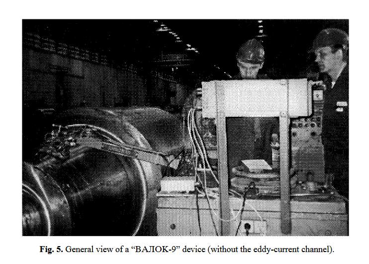
The nine-channel device ВАЛОК-9 offers the larg-est functionality (Fig. 5). This device has no analogues.It has been designed for the comprehensive testing ofrolls and can be used for inspecting thick-walled pipes,cylindrical items, etc., which are 300–2000 mm indiameter. Only slight modifications are needed to use itfor cylindrical articles with other diameters.
Depending on the ratio of the peripheral velocity ofrotation of an object and the linear movement of thesliding carriage, testing can be carried out during oneor several runs of the acoustic unit along the generatrix.To increase the probability of detecting differently ori-ented flaws, the device uses eight ultrasonic PETs withdifferent input angles.
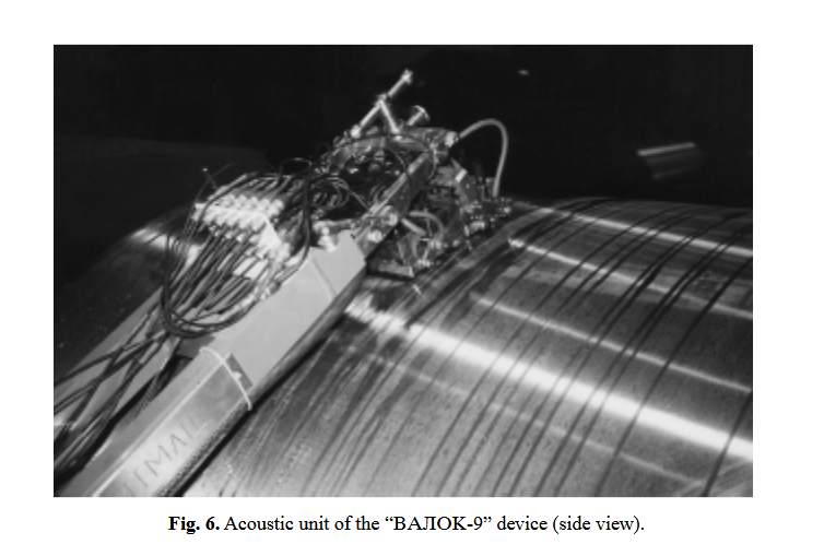
The direct combined PET and transmitter-receiver PET are intended for detecting bulk flaws and planarflaws oriented parallel to the generatrix. The sonication depth of the direct transducer equals half the bodydiameter. Angle PETs with input angles of 40 and 50° are intended for detecting bulk and vertically-orientedflaws at depths down to the axial line of the roll body. Angle PETs with input angles of 60 and 70° areintended for detecting flaws at depths down to 0.4 and 0.2 of the body radius, respectively. The PET for headwaves is intended for detecting vertically oriented cracks close to the surface, including those under welds(Fig. 6).
The same scanning range is used to test roll necks and bodies. This makes it possible to detect flaws inroll bodies when testing roll necks. Presumably, this might have resulted in false echo signals; however,experiments on rolls showed that no false echo signals were observed. The subsequent experience of workwith the devices confirmed the correctness of this approach.
The device is designed as a dustproof and moistureproof monoblock unit, which is arranged on a freearea of the frame (plate) of a roll-grinding machine, with a detachable scanning mechanism installed on a sliding carriage with the acoustic unit. There is also a design variety that ensures easy mounting of thedevice on a wall, as well as easy dismounting.
The nine-channel flaw detector features a system of temporary sensitivity adjustments and is equippedwith a color display; it has a convenient and easy-to-use user interface.
After testing, the results are analyzed in a separate room. To increase the testing productivity, thetesting data are automatically transferred via a local network to a computer where a 3D model of theroll is plotted.
The software of the device ensures the fast processing and real-time saving of the data. If required,it is possible to turn any channel on or off. Roll necks and bodies are inspected separately. During aninspection, the outline of a roll is output to the display together with an image of the acoustic unit mov-ing in real time.The scanning mechanism is intended for attaching the acoustic unit to the roll surface; it is mounted ona free area of the machine’s sliding carriage.
The scanning mechanism comprises a turning table and a hand-operated reducing gear for lifting and lowering the arm support with the acoustic unit. The turning table isequipped with a latch that locks the arm in different orientations in the horizontal plane, in particular, strictlyat right angle to the generatrix. The turning table is used to prevent the acoustic system from interfering withthe grinder’s working operations when it is not used.
At the end of the arm, there is a suspension part of the acoustic unit, which accommodates the piezoelec-tric transducers. All PETs are grouped in carriers, with two PETs in each. Each carrier has an independentgimbal suspension. The original design of the acoustic unit ensures the same pressure on each carrier withthe PETs; this design is patented [4].
The device is equipped with an eddy-current testing channel for detecting surface and subsurface flawslocated down to 2 mm deep. The testing results are processed by a visualization program and imposed onthe results of ultrasonic testing.
Automated Devices - Comparison Of Parameters Of Automated Devices For Testing Mill Rolls
| Manufacturer | Roll material | Testing methods | Direct transducer | Angle transducer | Elements tested | Testing depth | Positioning accuracy | Availability of temporary sensitivity adjustment | Data output | |||
|---|---|---|---|---|---|---|---|---|---|---|---|---|
| Surface flaws | Internal flaws | Roll body | Roll neck | |||||||||
| TsNIITMASh ВАЛОК-2 | Cast iron, steel | Eddy-current and ultrasonic | + | - | + | + | + | + | 0–150 | ±5 mm | + | Topography of flawson a two-dimensional developed view of a roll |
| TsNIITMASh ВАЛОК-5 | Cast iron, steel | Eddy-current and ultrasonic | + | + | + | + | + | + | From 0 to the body radius | ±2 mm | + | Topography of flawson a three-dimensional model of a roll |
| TsNIITMASh ВАЛОК-9 | Cast iron, steel | Eddy-current and ultrasonic | + | + | + | + | + | + | From 0 to the body radius | ±2 mm | + | Topography of flawson a three-dimensional model of a roll |
| LISMAR (Netherlands) | Cast iron, steel | Eddy-current and ultrasonic | + | - | + | + | + | - | 0–1700 | No data | - | Topography of flawson a two-dimensional developed view of a roll |
| SARCLAD (Great Britain) | Cast iron, steel | Eddy-current and ultrasonic | + | - | + | + | + | - | 0–150 | Angular 45°; linear 12–50 mm | - | Topography of flawson a two-dimensional developed view of a roll |
| Kantoc (Japan) | Cast iron, steel | Ultrasonic | - | + | + | - | + | - | 0–5 | No data | - | Topography of flawson a two-dimensional developed view of a roll |
| Innerspec Tech-nologies Inc. (USA) | Cast iron, steel | Ultrasonic (EMAC) | - | - | + | - | + | - | 0–2 | No data | - | Topography of flawson a two-dimensional developed view of a roll |
The computer system acquires data from the ultrasonic transducers and from the position sensors.The positioning system consists of absolute rotation sensors and cross-movement sensors. In case of amachine failure or unexpected shutdown, it is not necessary to start the testing anew. The testing isstarted from the position where the machine stopped last time. The rotation sensor is mounted insidethe machine hood; it is connected with the rotation of the shaft via a gear system. The horizontal dis-placement sensor is mounted on the sliding carriage and is directly connected with its shaft via a gearsystem. The gear system prevents slipping during the acquisition of coordinates.
Based on the data obtained, the software operating under Windows plots a 3D model of the roll. The visu-alization program makes it possible to rotate the 3D model in three dimensions. It is also possible to obtainany cross section in a radial plane. An NDT inspector can measure and select zones with flaws and deter-mine their areas. All selected cross sections and views of harmful flaws are stored as tabs together with thetesting data files.
After studying the results of testing at different sensitivity levels, an NDT inspector prepares a decision.All testing results are stored on the hard disk of the computer and can be recorded on a CD or on othermedia.
The "ВАЛОК-5" device occupies an intermediate place in the model series.
Its main field of application is the testing of cast-iron rolls. Its main technical characteristics and visual-ization method are the same as those of ВАЛОК-9.
The ultrasonic testing is carried out on four channels. One channel is used for eddy-current testing.
The use of ВАЛОК-type devices makes it possible to perform the primary certification of rolls; increasethe testing productivity; improve the testing thoroughness, in particular, to increase the probability of detect-ing differently-oriented flaws and prevent emergency situations; and monitor the development of flaws dur-ing the operation.
We estimate that the pay-off period of automated devices for testing mill rolls ranges from 6 to 18 months, depending on the model.
